


 May 27,2026
Last month, a manufacturing plant faced a hefty $12,000 back-charge from its electric utility—not for excessive consumption, but for months of inaccurate metering caused by one poorly mounted medium-voltage current transformer. The manager sighed, “We assumed it was just like a low-voltage clamp.” This assumption, shared by many field technicians, can lead to billing disputes, safety incidents, and even damage to connected metering equipment.
Installing a medium-voltage current transformer for metering requires more than mechanical fastening. It demands careful attention to ratio, burden, polarity, and wiring integrity—all within the framework of applicable standards such as IEC 61869-2 and IEEE C57.13. Whether you’re upgrading a switchgear metering panel or fitting a new feeder, a methodical setup protects revenue accuracy and keeps your electrical asset management audit-ready.
If you’d rather start with hardware that eliminates many field wiring uncertainties, pre-tested metering transformers from a dedicated manufacturer can save hours on site. Let’s walk through each phase of a successful installation.
1. Interpret the Metering Specification and CT Parameters
Before touching any busbar, pull out the single-line diagram and the meter’s data sheet. The key figures you need:
-
Primary current rating: e.g., 600 A, 1200 A, matching the feeder’s normal load.
-
Secondary current: typically 5 A or 1 A.
-
Accuracy class: metering applications often require Class 0.5S or 0.2S according to IEC 61869-2, ensuring low error between 5% and 120% of rated current.
-
Burden (VA): the total load the secondary circuit presents to the transformer. Exceeding the rated burden degrades accuracy.
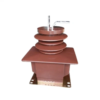
One pitfall here is “over-rating.” Selecting a 2000:5 A unit for a feeder that rarely exceeds 300 A forces the metering CT to operate in its least accurate region. Always match the continuous thermal current to the expected load profile. A physical check of the nameplate, comparing the documented ratio and class against the purchase order, eliminates a common source of mismatch. While CT transformers (1/3) are widely available, the exact combination of accuracy and burden must be verified with the vendor’s test report.
2. De-energize, Verify, and Prepare the Mounting Area
Safety is non-negotiable. Lock out the feeder, test for absence of voltage, and apply portable grounds if required by your site procedure. In many MV switchgear compartments, space is tight, so plan the physical routing of the secondary leads before you lift the transformer into place.
When handling wound-primary or bar-type transformers, inspect the insulation for any hairline cracks. Even a minor epoxy damage can lead to partial discharge under operating voltage. I recall a site where a chipped insulation surface went unnoticed; three months later, the CT failed during a humidity surge, taking the revenue meter offline. A five-minute visual check and insulation resistance test (using a 1000 V megger on the secondary winding) can prevent that.
3. Mount the Transformer with Correct Orientation
Orient the transformer so that the primary marking (usually P1) faces the line side and P2 faces the load side. In ring-type transformers, this may be indicated by a label or a cast-in arrow. Secure the unit to the busbar or cable using the provided hardware—torquing to the manufacturer’s specification prevents partial contact that causes local heating.
Pay special attention to the mechanical alignment. A tilted CT on a vertical busbar can shift under vibration and abrade the secondary lead insulation. Use anti-vibration clamps or tie-wrap anchors where the installation is subject to mechanical shock.
Once the mechanical assembly is solid, route the secondary terminals S1 and S2 to the terminal block. At this stage, many engineers choose to explore pre-assembled metering transformer assemblies that arrive with factory-configured shorting links, cutting wiring time dramatically and reducing the risk of open circuits.
4. Wire the Secondary Circuit with Precision
The secondary wiring is the nervous system of the metering chain. Use stranded copper wire of at least 2.5 mm² (14 AWG) with an insulation rating appropriate for the metering panel voltage. A shielded twisted pair is recommended when the meter is far from the CT or in electrically noisy environments; the shield must be grounded at one end only to avoid ground loops.
The cardinal rule: never leave the CT secondary open-circuited while primary current is flowing. Even a momentary open circuit can generate hazardous voltages and permanently damage the transformer’s core. Always land the secondary leads on a shorting terminal block or test switch that shorts the CT before it reaches the meter. Wire S1 to the corresponding polarity mark on the meter’s current input and S2 to the other terminal, maintaining correct polarity. Reversing S1 and S2 causes the meter to read reverse power flow, often flagged as a tamper event by utility billing systems.
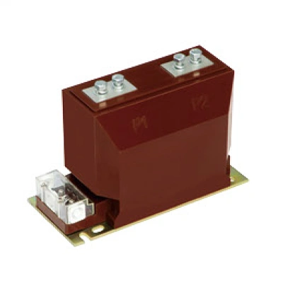
Here, CT transformers (2/3) frequently cause confusion because their secondary terminals are not always clearly labeled for metering vs. protection applications. Check the wiring diagram included in the documentation—if in doubt, a quick primary injection test will confirm polarity.
5. Commissioning Tests and Power-On Verification
Before re-energizing, perform three checks:
-
Ratio test: Inject a known low-voltage current (e.g., 10 A primary from a portable test set) and measure the secondary output. Compare against the nameplate ratio.
-
Polarity test: Use a DC pulse method or a battery-and-analog-meter flick test. A correct connection shows a positive deflection on the meter when the circuit is established.
-
Insulation resistance: Megger the secondary winding to ground. A reading below 50 MΩ warrants investigation.
Once the feeder is live at low load, verify the meter registers positive active power and that the measured current roughly matches an independently placed clamp meter. Log the readings for a few hours under varying load conditions to confirm the total vector error stays within the class limits.
During these checks, mistakes like a missing shorting link before disconnecting the meter become painfully obvious—and expensive. A simple laminated checklist at the panel reduces the error rate dramatically.
Common Pitfalls and How to Steer Clear
Wrong ratio selection for the application. Revenue meters demand a CT that remains linear across the load span. If a feeder’s minimum load drops below 5% of the CT primary rating, the accuracy error can balloon. Always model the load profile before procurement.
Overburdened secondary loop. Every meter, lead, and connection adds impedance. Calculate the total burden at the secondary terminals and stay below 75% of the CT’s rated burden to leave headroom. A typical 0.5S class CT rated 10 VA will perform poorly if the wiring alone dissipates 8 VA.
Undocumented polarity exchange. When multiple CTs are exchanged during retrofits, the secondary leads sometimes get swapped. Always tag the leads with “S1” and “S2” and use heat-shrink labels. A utility revenue protection audit will penalize a polarity swap even if the energy total remains correct by accident.
When all these variables start to feel overwhelming, factory-tested instrument transformers that ship with individualized calibration certificates can move much of the quality assurance upstream. In a recent brownfield metering upgrade, using a pre-certified kit reduced on-site commissioning time from two days to four hours.
Taking Your Setup Further
For facilities moving toward advanced energy management, consider specifying transformers with dual secondary windings—one for metering, another for power quality analysis. This avoids duplicating hardware and creates a clean separation between billing data and internal analytics. Smart meters with digital communication interfaces (Modbus, IEC 61850) can also accept low-energy analog signals from compliant sensors, minimizing wiring interference.
No matter how sophisticated the equipment, the foundation remains a precisely installed medium-voltage current transformer. Without mechanical and electrical integrity at this first link, all downstream data is suspect.
If you’re planning a new metering installation or retrofitting older panels, Fuyi’s metering transformer selection guide provides a straightforward walkthrough to match your feeder characteristics with the right instrument set. With pre-configured shorting blocks, type-tested accuracy, and clear documentation, it helps you bypass the most common setup errors and keep the utility meter—and your finance team—happy.
This article offers general guidance only. Always follow local electrical codes, manufacturer instructions, and your organization’s safety rules when working on medium-voltage equipment.



-Temperature-Controller-1.webp)