Jul 04,2026
There’s a quiet routine that unfolds every morning in well-run substations. Before the shift briefing ends, a technician walks the yard with a clipboard and a thermal camera, pausing longest in front of the medium voltage switchgear and the tall, polymer-housed units standing guard against transient overvoltages. One of the first numbers they write down is the leakage current reading. No alarm bells are ringing, nothing has tripped overnight, yet they still check it. They do it because they know that this single value — stable, uneventful, and often overlooked — separates a reliable installation from one heading for a failure that no one saw coming.
Why the Morning Check Matters
After a decade of working alongside field service teams, I’ve learned that the most expensive failures are rarely the dramatic ones. They’re the slow-motion breakdowns that could have been caught with a three-minute daily check. A medium voltage lightning arrester is designed to handle surges silently, absorbing energy and returning to its high-impedance state within microseconds. But when its metal-oxide varistor stack begins to degrade — due to moisture ingress, repeated stress, or simple aging — the leakage current starts to climb. That rising resistive component generates heat. Heat accelerates aging. Aging pushes the unit towards thermal runaway. By the time the protective device fails short circuit, the damage has often spread to adjacent equipment. This is why introducing a disciplined, three-step daily examination focused on leakage current is one of the most cost-effective maintenance strategies an electrical reliability program can adopt.
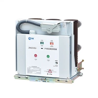
This simple practice is not just about recording a number. It is about understanding the health of your overvoltage protection assets before a fault occurs. If the equipment feeding your readings is outdated or lacks diagnostic-friendly features, upgrading to modern, monitoring-ready protection devices can make these daily checks faster and far more revealing. Exploring modern diagnostic-ready overvoltage protection designs often reveals built-in measurement taps and durable housing that simplify this exact morning routine.
Check #1: Is the Leakage Current Staying Within Its Baseline?
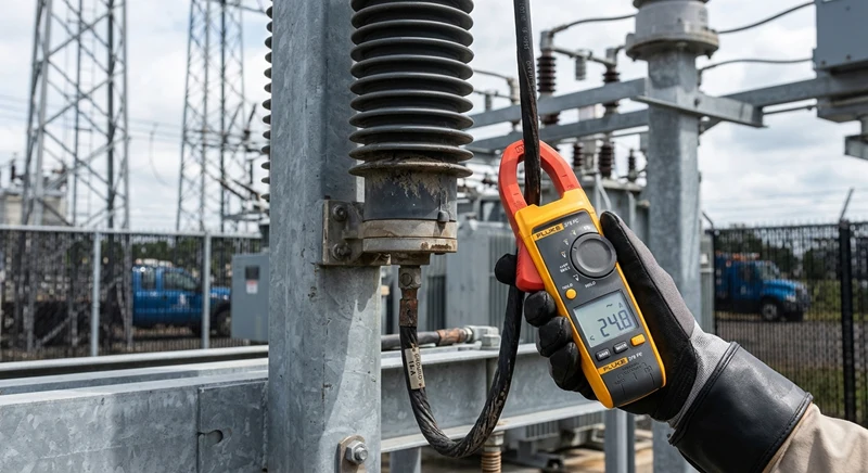
Your first look each day should be at the total leakage current magnitude and, if your monitoring setup allows, its resistive component. A healthy metal-oxide unit under normal operating voltage draws a predominantly capacitive current, typically in the low milliamp range, with a resistive part perhaps 10–20% of that. The critical warning sign is not the absolute value — it’s the trend.
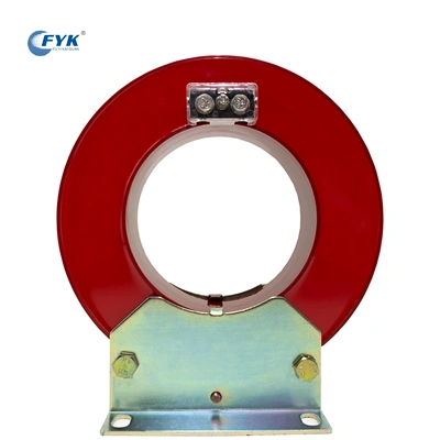
Write the numbers down. Create a simple spreadsheet or use the data trending feature in your maintenance management system. A sudden step change of 10–15% from the baseline, even if the reading remains below the manufacturer’s stated limit, is enough to trigger an infrared scan. More significantly, watch the resistive current. Because the resistive component represents the actual power loss inside the varistor column, a steady upward drift indicates that the grain boundaries in the ZnO elements are changing chemically. IEC 60099-5 emphasizes that resistive current measurement, especially third harmonic analysis, offers one of the earliest indicators of degradation. Don’t wait for the total current to double. Act on the drift.
Field experience has taught me that humidity, surface contamination, and even a passing rain shower can temporarily influence the reading. That’s why the next check is just as important as the first.
Check #2: How Are Environmental Conditions Skewing Your Reading?
A technician I trained once called in a panic because the leakage current on a healthy unit had jumped 20% overnight. The cause was morning dew combined with a light layer of salt spray from a nearby coastal road. The housing surface leakage was contaminating the measurement. This is not a failure; it’s an environmental artifact. However, if you don’t know to look for it, you might either ignore a genuine internal problem or waste time investigating a clean unit.
The daily check therefore must include a quick visual and operational note on the weather, ambient temperature, and any visible pollution on the housing. If your monitoring system compensates for surface leakage through a guard ring or dedicated third-wire measurement, verify that this compensation circuit is functional. If you are measuring via a simple ground lead current transformer without surface leakage rejection, always clean the housing before taking a diagnostic reading after rain or heavy fog. Adopt a habit of comparing the reading on a foggy Monday with the reading from the previous clear Friday only after the housing has been gently wiped with a dry cloth. This discipline helps isolate true internal degradation from seasonal noise.
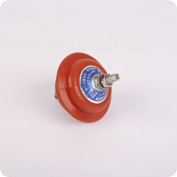
Reliable polymeric-housed overvoltage protection equipment with optimized creepage profiles tends to maintain stable surface characteristics even in polluted environments, minimizing the influence of external leakage on your readings. This design consideration directly supports the accuracy of your daily check.
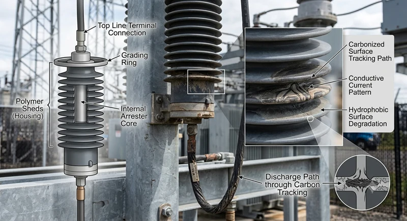
Check #3: Are the Connections, Housing, and Disconnector Intact?
Leakage current can be influenced by far more than the internal varistor blocks. A loose ground connection, a cracked housing, or a partially operated disconnector can alter the path of the measuring current or mask a developing internal fault. Walk around the unit and look for:
-
Discoloration or tracking marks on the polymer sheds.
-
Cracks or abrasion from wildlife or wind-blown debris.
-
Tightness and corrosion state of the ground lead terminal. A high-resistance ground connection can reduce measured leakage current, falsely reassuring you while the arrester body potential rises.
-
The condition of the grading ring or corona cap, if fitted. A missing or deformed grading ring changes the voltage distribution along the column and can shift the leakage current reading.
Include a quick thermal scan with your infrared camera. Even a one-degree temperature rise on one section, compared to an adjacent identical unit on the same bus, is meaningful. The temperature pattern should be uniform. Hot spots near the top may indicate moisture ingress; overall warmth suggests elevated resistive losses. Combine the thermal image with the resistive current trend and you now have a multi-parameter view of asset health that far exceeds a simple pass/fail checklist.
What Daily Checks Won’t Tell You (And What to Do About It)
Even a disciplined daily routine focused on leakage current has blind spots. It doesn’t measure the residual voltage during a fast-front transient. It doesn’t confirm the arrester’s energy handling capability unless a surge event happens to occur. And it won’t detect a manufacturing defect that lies dormant until stressed by a genuine overvoltage. This is why daily monitoring should slot into a layered reliability strategy: daily leakage current checks, quarterly infrared thermography, annual offline testing (such as the 1 mA DC reference voltage test), and immediate investigation after any severe storm or switching event.
One common mistake is fixating on the leakage current number without logging the voltage at the time of measurement. System voltage fluctuations of a few percent can change the capacitive component markedly. Always note the bus voltage, or, for a more robust approach, use diagnostic instruments that calculate the resistive component independent of voltage normalization. This keeps your trend analysis honest.
Moving from Reactive to Predictive
When you’ve built a reliable baseline of three-point daily checks — trending total and resistive leakage current, noting environmental factors, and confirming physical integrity — you shift from reacting to alarms to anticipating them. The units that once worried you become predictable. The ones that demand a closer look give you weeks, not seconds, of warning. That’s the kind of confidence that lets you plan an outage on your schedule, not the grid’s.
If you want to deepen this predictive capability, exploring condition-based monitoring tools designed for medium voltage networks can integrate data logging and trend visualization directly into the protection device, making the daily check a matter of reading a local display or a wireless data feed rather than interpreting raw milliamp values alone.
At the end of the day, a medium voltage lightning arrester is a silent, humble component. It doesn’t rotate, it doesn’t sing, and it doesn’t scream when it’s hurting — it just gets a little warmer and a little more lossy each month until the numbers on that morning log tell the story. Listening to those numbers is what makes the difference between a five-minute maintenance entry and an eight-hour forced outage. For engineers who believe that reliability is built on small, consistent habits rather than dramatic gestures, these three checks are a good place to start.
Disclaimer: This article provides general guidance based on industry practice and should not replace manufacturer-specific manuals or local safety regulations. Always follow site electrical safety procedures and consult qualified engineers before performing live measurements.