 Jun 17,2026
Last Wednesday, Mark, a maintenance electrician at a mid-sized manufacturing plant, noticed something odd on the control room display. One of the feeder ammeters had dropped to zero while the motor it monitored was clearly running under load. His first instinct was to blame a faulty meter. A colleague with more field experience stopped him: “Before you touch anything, check the CT secondary — if it’s open, you’re sitting on a high-voltage trap.” That warning probably saved Mark from a serious arc flash incident. The problem was a loose terminal deep inside a junction box, and the open secondary had been silently stressing the insulation for days. If you work with metering circuits, protection relays, or any kind of measurement chain, this scenario is more common than you’d think. Here’s how to detect an open CT secondary, fix it methodically, and stop it from happening again.
Why an Open Secondary is Dangerous
In normal operation, the secondary winding of a measurement transformer is almost in a short-circuit state — the burden (relay or meter) is a low-impedance load. When that path breaks, the primary current keeps flowing, and the entire magnetic core saturates sharply. The result: a very high induced voltage at the secondary terminals, often reaching several kilovolts even in medium-voltage switchgear. This voltage can break down wiring insulation, damage connected instruments, and pose a direct shock hazard. Thermal runaway follows quickly as the core overheats, which can permanently degrade the winding insulation and turn a minor wiring fault into a complete equipment replacement. Understanding this mechanism — described in detail in IEC 61869-2 for inductive instrument units — makes it clear why you never want to run a metering loop with an open secondary, even for a few minutes.
Step 1 – Recognize the Symptoms Early
Before you open any panel, look for telltale signs:
-
Zero or fluctuating reading on an ammeter that should show a steady load current.
-
Buzzing or hissing sound near the terminal block, caused by partial discharge or arcing across a loose connection.
-
Burned smell or discoloration around the secondary terminals or wire insulation.
-
Unexplained relay tripping in protection circuits, especially earth-fault or differential relays that suddenly lose one current input.
If you work with three-phase metering, compare all three phase readings. A single-phase drop to near zero while the other two remain normal is a strong indicator of an open circuit somewhere on that channel. At this stage, treat every secondary wire as potentially energized with lethal voltage.
Step 2 – Confirm the Open Circuit Safely
Never disconnect secondary leads while current flows in the primary conductor. The golden rule: short the secondary before you break any connection. But first you need to confirm the open is real and find its location.
A. Non-contact thermal scan
Run an infrared camera or spot thermometer over accessible terminal blocks. An open-circuit condition causes the core and sometimes the secondary leads to heat up significantly. A healthy measurement loop should show only a mild temperature rise compared to ambient.
B. Clamp-on current measurement
Use a true-RMS clamp meter on the secondary wiring. If the primary is known to be carrying current but the secondary loop shows zero or erratic milliamps, the circuit is interrupted somewhere. This method keeps you hands-free and avoids touching any terminals — the safest first check.
C. Burden voltage check (only if qualified and with adequate PPE)
With the secondary loop still closed, measure the AC voltage across the burden (right at the meter or relay terminals). It should typically be a few volts at most. If you see tens of volts or a voltage that fluctuates wildly between zero and a high value, the connection is intermittent or fully open upstream of that point.
Once you’ve located the faulty segment, isolate the primary current — open the corresponding breaker or de-energize the feeder — before proceeding to any wiring repair.
Step 3 – Fix the Open Circuit Methodically
-
Install a temporary shorting link. Before touching any terminal, verify zero primary current. Then apply a shorting wire or an approved shorting block directly on the secondary terminals of the unit. This protects the winding if you accidentally break the external circuit during the repair.
-
Track the wiring path. Start from the shorting point at the secondary terminals and work outward toward the burden. Look for loose screw connections, corroded crimps, broken wires inside cable conduits, or a failed test switch that was left in the wrong position. In nine out of ten field cases, the culprit is a terminal screw that gradually worked loose due to vibration.
-
Replace damaged components. If insulation looks charred, brittle, or cracked, cut back the wire to a healthy section or pull a new control wire. Never tape over heat-damaged insulation — it will fail again. For terminals, use ring-type lugs with proper crimping tools rather than bare wire under a screw, which tends to loosen over time.
-
Remove the shorting link only when the loop is complete. Double-check that the burden is connected and the full circuit from secondary winding back to the terminals is intact. Remove the shorting wire. Slowly re-energize the primary circuit and verify the ammeter shows the expected value.
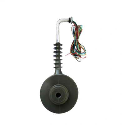
One common mistake worth highlighting: some technicians try to troubleshoot an open CT secondary while the primary is still live by “quickly” measuring voltage. This exposes you to dangerous peaks and can push a healthy unit into permanent insulation damage. If your setup demands live troubleshooting, consider using permanently installed components that meet IEC 61869 safety margins — you can view Fuyi’s IEC-compliant instrument transformers designed to withstand the mechanical and thermal stress of real-world industrial environments.
Step 4 – Prevent Recurrence
After the repair, make these preventive steps part of your routine:
-
Torque terminals annually. Loose connections are the dominant root cause. Use a calibrated torque screwdriver according to the terminal block manufacturer’s specification. Re-torque all secondary terminals during scheduled shutdowns.
-
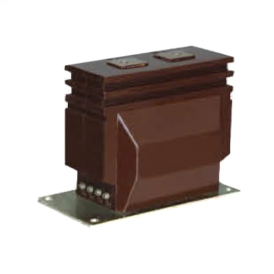
Use shorting-type terminal blocks. These blocks automatically short the secondary when the disconnect plug is removed, greatly reducing the risk during maintenance. They are a simple retrofit on most panels. If you want to explore built-in protection options, browse Fuyi’s CT/PT units with integrated open-circuit safeguards.
-
Label wiring clearly. Every secondary circuit should be marked with its origin and destination. When a fault occurs at 2 a.m., clear labeling saves minutes — and fingers.
-
Include CT open-circuit checks in your thermographic survey. An annual infrared scan of all accessible metering compartments catches loose terminals long before they become opens.
A Field Insight: When Quality Components Make the Difference
I recall a water treatment plant where the maintenance team kept chasing intermittent differential trips for months. The problem would mysteriously disappear after a few hours, only to resurface in humid weather. Eventually, a thorough teardown revealed that moisture had been creeping into a poorly sealed secondary junction box, corroding the terminal block. Replacing the generic terminals with sealed, high-quality units resolved the issue permanently. The takeaway is simple: an open secondary is not always just about torque — material selection and enclosure sealing play a huge role in long-term reliability. If you are specifying components for a new panel or a retrofit, it pays to look beyond the initial purchase price and evaluate sealing integrity, terminal design, and compliance testing documentation.
Getting the Right Parts Without the Guesswork
Detecting and fixing an open secondary is only half the battle. The long-term fix often involves upgrading the metering chain with components that can handle the environment they sit in. Whether you are building a new switchgear lineup or refreshing an aging control room, choosing solidly constructed measurement components reduces those 2 a.m. callouts.
If you’re planning such an upgrade, get expert guidance on Fuyi’s CT and PT range — their technical team can help you match burden, accuracy class, and physical footprint to your exact application, so you spend less time chasing wiring faults and more time focusing on the process.
References and standards:
-
IEC 61869-2: Additional requirements for current transformers.
-
IEEE C57.13: Standard requirements for instrument transformers.
-
NFPA 70E: Standard for electrical safety in the workplace.
Disclaimer: This article is for informational purposes only. All high-voltage troubleshooting must be performed by qualified personnel wearing appropriate PPE and following your local safety regulations.


-Temperature-Controller-1.webp)