Jun 25,2026
A utility in the Midwest learned the hard way that a single reversed wire can cost a facility tens of thousands of dollars in billing disputes. Their metering setup had been in service for nearly two years before an audit flagged a 14% discrepancy. The root cause? The polarity of one medium voltage instrument transformer had been flipped during a routine switchgear upgrade, and no one had re-run the basic burden and polarity tests.
Stories like this are more common than most engineers like to admit. Revenue metering at medium voltage (1 kV to 36 kV, typically) demands a combination of the right hardware, a disciplined installation process, and a healthy skepticism toward “it was working before.” This article breaks down that process into manageable steps, highlights the standards you need to keep within arm’s reach, and shows where things usually go wrong — so you can get accurate readings from the first power-up.
Before You Touch a Terminal: Select the Right Measuring Device
Walk into any electrical room and you’ll hear people use “metering CT” as a catch-all phrase. But not every device that scales down primary current is suitable for billing or precise energy management. The first decision tree revolves around accuracy.
For revenue metering, both IEC and IEEE standards define specific accuracy classes. Under IEC 61869-2, class 0.2S or 0.5S is typical for billing applications where the load can vary widely; the “S” designation means the device maintains its specified error limits from 1% to 120% of rated current. IEEE C57.13-2016 uses a different naming convention (0.15, 0.3, 0.6 with burden ratings), but the principle is the same: you need a device whose accuracy is guaranteed over a wide dynamic range, not just at full load.
Key parameters to check before ordering:
-
Rated primary current: Select a ratio that places your typical operating current between 20% and 80% of the primary rating. Oversizing a 3000:5 unit for a feeder that rarely exceeds 200 A will push measurements into the low-end error band.
-
Burden: The total VA of the connected secondary loop — including the meter, wiring, and connection losses — must stay within the device’s rated burden. Undersized secondary wiring is a chronic source of saturation and drift.
-
Rated short-time thermal current (Ith): Must exceed the maximum prospective fault current at the point of installation. This is a safety and longevity parameter, not just a compliance checkbox.
-
Insulation level: For 12 kV systems, typical rated insulation level is 28/75 kV (power-frequency/lightning impulse). Match it to your switchgear’s rating.
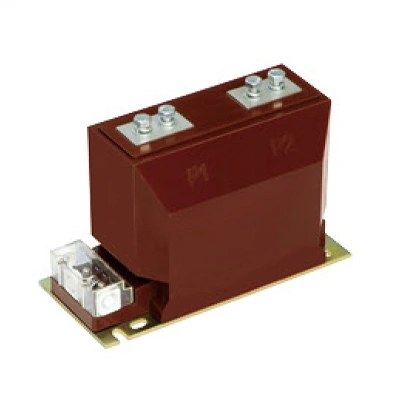
If your application combines metering with protection relaying, or if you plan to measure both voltage and current for a full energy picture, you may want to check the specific configurations of pre-integrated CT/PT metering units. Having both functions in one tested assembly saves panel space and avoids separate mounting and wiring errors.
Pre-Installation Checks — The Half-Hour That Saves a Weekend
Before any hardware gets mounted, confirm three things physically and electrically.
Physical inspection
-
Check the nameplate against your single-line diagram. Verify the ratio, accuracy class, and burden match your specification — not a similar project from last year.
-
Inspect the secondary terminals. On many medium voltage units, the secondary terminal box contains shorting links or test blocks. Make sure they are intact and finger-tight.
-
Look for any cracks in the resin body or porcelain insulator. Cast-resin units are tough, but hairline cracks from shipping shock can invite partial discharge later.
Polarity marks
Every measuring device of this type carries primary polarity marks (P1, P2) and secondary marks (S1, S2). Industry convention says: at the instant current flows from P1 to P2, current flows from S1 to S2 through the external burden. A missing or misunderstood polarity mark is the number one reason for negative energy readings. Circle the marks with a paint pen now — your commissioning engineer will thank you.
Insulation resistance test
Using a 1000 V or 2500 V megohmmeter, measure the insulation resistance between the primary winding and ground, and between the secondary winding and ground. There is no universal pass/fail number, but any reading below 100 MΩ on a clean, dry device warrants investigation. For new equipment, values in the gigaohm range are typical. Record the values as a baseline.

Step-by-Step Physical Installation
This is the portion where most tutorials jump straight to wiring, but mechanical integration into the switchgear determines both safety and accuracy.
Step 1: Mounting orientation
Medium voltage measuring devices are designed to be mounted on busbars, in dedicated metering cubicles, or on a panel frame. The primary conductor passes through the window or is connected to the primary terminals. If the unit is busbar-mounted, center the conductor in the window. Eccentric placement can introduce a few tenths of a percent error, which adds up in annual energy reconciliation.
Step 2: Primary connections
When the unit has primary terminals (rather than a window-type design), torque the bolted connections to the manufacturer’s specification. A loose primary connection generates localized heat that can crack the resin encapsulation and create a partial discharge site. Use a torque wrench, not an impact driver.
Step 3: Grounding
One terminal of the secondary winding must be grounded — and only one. This is a safety requirement (IEC 61869-1 Clause 5.3.4, IEEE C57.13 Clause 6.5). Grounding prevents the secondary circuit from floating to primary potential in the event of an insulation failure. In most installations, the S2 terminal is grounded at the first accessible point, typically inside the terminal box or at the test block.
Step 4: Secondary wiring
-
Run the secondary leads in dedicated, shielded twisted-pair cables, separated from high-voltage and control wiring by at least 200 mm.
-
Keep the secondary loop length as short as physically practical. Every meter of wire adds resistance to the burden, which directly affects accuracy. If the meter is 50 meters away, recalculate the total VA load to confirm it’s still within spec.
-
Never use wire nuts on secondary circuits; vibration loosens them. Use ring terminals with captive screws or spring-clamp terminals.
A frequent question arises here: “Can I run the secondary wiring through a common multicore cable?” Not if you value accuracy. Induced voltages from adjacent pairs and common-mode noise are difficult to filter out at the meter input. For high-quality measurements, a properly matched set of metering transformers and dedicated wiring accessories can eliminate many of these interferences before they affect your data.
Polarity and Burden Testing — No One Skips This Twice
With everything wired, but before energizing, run a polarity check and a burden measurement. These tests catch 90% of installation errors.
Polarity test (flick test)
Use a 9 V battery and an analog voltmeter. Connect the battery to the primary side (P1 positive, P2 negative, through a momentary pushbutton). Connect the voltmeter to the secondary terminals with the positive lead on S1 and negative on S2. When you momentarily close the primary circuit, the voltmeter needle should flick in the positive direction. A negative flick means the secondary connections are reversed — swap S1 and S2 at the terminal block and retest.
Burden measurement
Inject a known primary current with a primary injection test set, or use the utility’s commissioning equipment. Measure the secondary voltage drop across the entire loop, including the meter. Calculate the actual VA burden and compare it to the nameplate value. If the burden exceeds the rating, you have two options: reduce the loop resistance (shorter, thicker wires) or select a unit with a higher burden rating.
Ratio verification
If you have access to a ratio test set, verify the actual turns ratio at 100% and 25% of rated current. The error should fall within the device’s accuracy class limits. This is also the time to confirm that the nameplate ratio matches the meter’s programmed CT ratio. A 1000:5 unit with the meter set to 800:5 will produce a permanent 20% measurement error, and nobody wants that conversation with the finance department.
The Mistakes That Even Experienced Teams Make
Over years of commissioning reviews, a few recurring patterns emerge.
-
Open-circuited secondary: This is the cardinal sin. A measuring device designed to operate into a low impedance can develop dangerously high peak voltages at its secondary terminals if the circuit is opened while primary current flows. It also saturates the core, leaving residual magnetism that degrades accuracy until the core is demagnetized. Always short the secondary at the test block before disconnecting the meter.
-
Multiple grounds on the secondary circuit: One ground is safe. Two grounds at different points create a ground loop, and the circulating current at power-system harmonics can distort the measured waveform significantly. If you see a few percent error that varies with the weather, look for the second ground.
-
Ignoring the rated safety factor (FS): Metering units need a low instrument security factor (FS5 or FS10), meaning the core saturates at a modest overcurrent to protect the connected meter. Using a protection-class device (which has a high accuracy limit factor) for metering can expose the meter to destructive current during faults. Double-check that the nameplate says “metering,” not “protection.”
-
Mixing old and new devices on the same bus: Retrofitting one feeder with a modern 0.2S class unit while the incomer still uses an old 1.2 class device doesn’t make the billing more accurate. The sum of feeder measurements will never reconcile with the incomer reading. For a cohesive measurement architecture, explore pre-configured CT/PT metering sets that provide consistent accuracy across multiple feeders. This makes energy audits simpler and more defensible.
Commissioning and First Energization
After all tests are satisfactory, remove all temporary shorting links and grounds used during testing. Re-tighten all secondary terminal screws. Document the test results — polarity check waveforms, burden calculation sheets, insulation resistance values — and attach them to the switchgear maintenance file.
On first energization, observe the meter or monitoring system for a few minutes at low load. A negative active power reading is an immediate red flag and usually points to swapped polarity or a wiring cross between phases. Resolve it before putting the metering data into any billing or reconciliation system.
Keeping Measurements Reliable Over Time
Measuring devices in medium voltage service are often left untouched for a decade. That doesn’t mean they stay accurate.
-
Schedule periodic burden checks: Secondary wiring resistance increases over time due to terminal corrosion and contact wear. Even a 0.1 Ω increase can matter when the total rated burden is only a few VA.
-
Watch for partial discharge: In older switchgear, partial discharge on the primary side can couple noise into the secondary circuit. If your meter starts showing intermittent spikes that don’t correlate with the load, request a PD survey.
-
Validate ratio every 5–7 years: Core characteristics drift slightly with thermal aging and mechanical stress. A 0.1% per year drift might seem trivial, but over a 15-year asset life, it puts you outside the original accuracy class.
If you are responsible for a new metering installation or a retrofit that needs to hold up to regulatory scrutiny, it’s worth considering a design approach that minimizes field wiring complexity. Modern solutions that combine current and voltage measurement into a single, factory-tested unit remove several of the failure modes discussed above. For a deeper look at such integrated metering transformers, you can visit Fuyi’s CT/PT portfolio — not as a sales pitch, but as a reference for what is possible in terms of plug-and-play accuracy and reduced commissioning time.
Further Reading & References
-
IEC 61869-1:2023, Instrument transformers – Part 1: General requirements
-
IEC 61869-2:2012, Instrument transformers – Part 2: Additional requirements for current transformers
-
IEEE C57.13-2016, IEEE Standard for Requirements for Instrument Transformers
-
ANSI C12.20-2015, American National Standard for Electricity Meters — 0.1, 0.2, and 0.5 Accuracy Classes
Disclaimer: This guide is for informational purposes. Always follow your local electrical code, manufacturer’s installation instructions, and the requirements of your utility or authority having jurisdiction. Medium voltage equipment must be installed and maintained by qualified personnel.