


 Jul 27,2026
Current transformer (CT) errors mainly stem from core saturation, excessive secondary burden, or poor installation practices. These errors appear as ratio inaccuracies and phase displacement, which directly affect metering and protection. This guide explains why they happen, how to perform practical calibration checks, and what factors you can control to keep CTs operating within their accuracy class limits.
How Current Transformer Error Is Defined
Every current transformer has two primary error components:
-
Ratio error (current error): The deviation between the actual and rated transformation ratio, expressed as a percentage.
-
Phase displacement (phase angle error): The difference in phase between the primary and secondary current vectors, measured in minutes or centiradians.
Both are specified by the accuracy class (e.g., 0.5, 1.0, 5P) under defined burden and frequency conditions. If actual operating conditions differ, the errors may increase beyond the class limits.
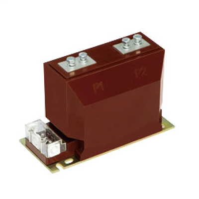
Common Causes of CT Errors
1. Secondary Burden Mismatch
The connected load (relays, meters, wiring resistance) forms the burden. Exceeding the rated burden drives the core toward saturation, raising ratio error and phase displacement. Even a long secondary cable run with insufficient cross‑section can add significant resistance.
Practical tip: Always calculate actual burden including cable impedance. A CT with a 5 VA rated burden may show noticeable error increase if the circuit consumes more than 3.75 VA under continuous load, as a safe margin.
2. Core Saturation Due to Overcurrent or DC Components
Overcurrents above the rated continuous thermal current, or transient DC offsets in fault conditions, can saturate the core. Once saturated, the secondary current waveform distorts, and protection relays may misoperate. For metering CTs, saturation leads to reading inaccuracies even at moderate overloads.
3. Remanent Magnetism
A CT core can retain residual magnetism after a heavy fault or a DC injection test. This remanence shifts the magnetizing curve, worsening errors especially at low currents. Degaussing is required before returning to service.
4. Incorrect Installation and Wiring
Reversed polarity, loose connections, or placing the CT near high magnetic fields from adjacent busbars can induce measurement noise and phase shifts. Mechanical stress on the core also changes its magnetic properties slightly.
5. Frequency Variation
Accuracy class limits are guaranteed at rated frequency (50/60 Hz). Off‑frequency operation, particularly in railway or marine applications, changes the excitation impedance and error profile. The effect is usually negligible within ±5% of rated frequency but must be verified for wider deviations.
6. Temperature Influence
Ambient temperature extremes affect winding resistance and core permeability. Manufacturers typically state the compensation range; outside that, the errors may drift.
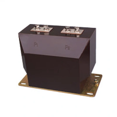
Practical Calibration Methods
Field calibration does not mean adjusting the CT itself (most are sealed and non‑adjustable), but verifying its performance against a reference standard. If errors exceed class limits, the CT must be replaced or the circuit conditions corrected.
Comparison Method (Most Common)
A calibrated reference CT of higher accuracy class is connected in series with the test CT, and both feed a comparator or digital bridge. The device directly measures ratio error and phase displacement.
Basic setup steps:
-
Ensure both primary windings carry the same current loop.
-
Connect the test CT secondary to the comparator input via proper burden (simulating actual load).
-
Inject current at 1%, 5%, 20%, 50%, 100%, and 120% of rated primary current, at rated frequency.
-
Record errors at each point and compare with the accuracy class limits specified in IEC 61869-2 or IEEE C57.13.
If a precise comparator is not available, a high‑accuracy ammeter and phase angle meter can be used, but combined uncertainty must be calculated.
Voltage Injection Method (For Laboratory Checking)
This indirect method applies a voltage to the secondary winding to simulate primary current, useful for quick core condition checks. It cannot replace a full comparison test but helps identify inter‑turn shorts or severe core degradation.
Calibration Checklist
Use the following checklist before any on‑site calibration:
- Verify reference CT has valid calibration certificate and accuracy class at least two grades better than the test CT.
- Confirm that the burden connected during test represents the actual operational burden (including relay and meter impedance plus cable).
- Measure and record ambient temperature and frequency.
- Demagnetize the test CT core before starting the test, especially if it was previously exposed to high current or DC.
- Check secondary wiring integrity: no loose terminals, correct polarity, grounding at one point only per design.
- Perform a visual inspection for core lamination cracks or corrosion.
- Document primary and secondary current readings in a test report table.
Error vs. Accuracy Class – A Quick Reference Table
| Accuracy Class | Ratio Error Limit (±%) at Rated Current | Phase Displacement Limit (minutes) at Rated Current | Typical Application |
|---|---|---|---|
| 0.1 | 0.1 | 5 | Laboratory standard |
| 0.2S | 0.2 | 10 | Precision metering |
| 0.5 | 0.5 | 30 | Commercial metering |
| 1.0 | 1.0 | 60 | Industrial metering |
| 5P | 1.0 (at rated accuracy limit current) | 60 | General protection |
| 10P | 3.0 | 60 | Protection where high fault currents saturate |
Note: Limits are valid from 20% to 100% rated current for measuring CTs (specific classes may extend to 5% or 120%). For class S meters, low‑current performance is additionally defined. Always refer to the applicable standard.
If your installed CTs show errors beyond these limits after adjusting burden and demagnetizing, a hardware replacement may be required. Review the available configurations in the CT/PT transformers category to identify units with appropriate accuracy class and burden rating for your installation.
How to Minimize Errors in Daily Operation
-
Match the CT rated primary current as closely as possible to the actual maximum load current; a severely oversized CT operates at low flux and may under‑deliver accuracy.
-
Keep secondary leads as short as practical and use adequate conductor cross‑section to limit burden resistance.
-
Avoid routing CT secondary cables alongside high‑current power cables to minimize electromagnetic interference.
-
Schedule periodic calibration verification based on environmental severity – every 2‑4 years for clean indoor settings, annually for outdoor or high‑vibration installations.
Frequently Asked Questions
Q1: Can a CT be recalibrated if it drifts out of its accuracy class?
Most sealed instrument CTs are not adjustable. If errors exceed class limits after verifying correct burden and demagnetizing, the CT should be replaced. Laboratory reference CTs may have adjustable turns compensation, but this is rare in industrial units.
Q2: How does power factor affect CT error?
Power factor does not directly change CT ratio error, but phase displacement combined with a low power factor load in the secondary measurement circuit can produce significant power metering errors. This is why phase error limits are tighter for metering classes.
Q3: What is the difference between a measuring CT and a protection CT in error behavior?
Measuring CTs require high accuracy over a normal current range (5‑120% In) and are designed to saturate quickly above that to protect instruments. Protection CTs maintain linearity up to high multiples of rated current (e.g., 20‑30 times) to faithfully reproduce fault currents for relays, with error limits defined at the accuracy limit current.
Q4: Do CT errors increase with age?
Gradual degradation can occur due to moisture ingress, thermal cycling loosening core laminations, or corrosion at terminals. Routine testing can detect trends before errors exceed allowed limits.
Q5: Is on‑site calibration as accurate as laboratory calibration?
On‑site accuracy is limited by the reference equipment, uncontrolled temperature, and burden uncertainties. It is typically sufficient for verification to a class 0.5 or 1.0 level. For higher precision (class 0.2S or better), laboratory conditions are recommended.
Q6: How do I choose a CT that maintains accuracy under my actual burden?
First calculate the total secondary loop burden (cable resistance + device load). Then select a CT whose rated burden is at least 1.5 times that value, within the required accuracy class. You can check the technical specifications of CT/PT products to compare accuracy‑burden curves and find a suitable model.
Conclusion
Current transformer accuracy depends on the interplay of burden, core condition, frequency, and installation details. Start by verifying the actual secondary burden and demagnetizing the core before concluding that a CT is faulty. When errors persist beyond class limits, replacement with a properly rated unit is the most reliable solution. For applications where precision metering or critical protection is required, always confirm the accuracy‑burden performance with the supplier and schedule periodic calibration checks to catch drift early.


-Temperature-Controller-1.webp)