 Jun 04,2026
You are reviewing a one‑line diagram and a critical question stops you: should you specify a current limiting fuse or a circuit breaker for this feeder? Both will interrupt fault current, but they do it in fundamentally different ways — and the difference can mean either a minor disturbance or major equipment replacement. This article gives you a structured, vendor‑neutral framework to evaluate which protection strategy actually fits your system’s fault levels, coordination demands, and long‑term operational goals, without getting lost in sales pitches.
Understanding the Fundamental Difference: Energy Let‑Through and Interruption Speed
Before you compare list prices or enclosure sizes, you need to understand the one technical distinction that drives almost every other decision: energy let‑through.
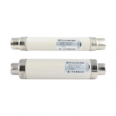
A current limiting fuse reacts so quickly that it interrupts the fault current within the first half‑cycle — well before the current reaches its prospective peak. The fuse element melts, an arc forms, and the circuit is fully cleared in a few milliseconds. The key result is a dramatic reduction in let‑through energy (I²t) , which directly lowers the thermal and mechanical stress that downstream equipment must survive.
A circuit breaker, even a modern magnetic‑only or electronic‑trip unit, still requires a mechanical operation sequence. Its total clearing time is typically several cycles. While it can safely interrupt the fault, it does not cut off the current before the first major peak, so the system absorbs higher let‑through energy.
| Protection Attribute | Current Limiting Fuse | Circuit Breaker |
|---|---|---|
| Typical interrupting speed | 1/4 to 1/2 cycle (sub‑cycle) | 3 to 8 cycles (depending on type) |
| Let‑through energy (I²t) | Extremely low – peak current is limited | Moderate to high – peak current passes through |
| Current limiting capability | Yes – stops peak current before it fully develops | No – current can reach full prospective value |
| Resettability | No – fuse must be replaced after operation | Yes – can be reclosed immediately |
| Remote operation | No (fuse + switch combinations add remote operation) | Yes – integral motor or shunt operation |
| Maintenance frequency | Virtually zero after commissioning | Periodic exercising and testing recommended |
What this means for you: If your equipment has a low short‑circuit withstand rating, reducing I²t by over 90% can be the difference between keeping a busbar intact or replacing melted conductors. As defined in the IEC 60282‑1 standard, current‑limiting fuses must clear high fault currents before the first peak, which is the mechanism that delivers this protection. When you are assessing whether your switchgear can withstand a fault, the fuse’s sub‑cycle operation becomes a design tool, not just a safety device. You can examine how specific current‑limiting fuse designs accomplish this sub‑cycle interruption in medium‑voltage systems to see how they suppress peak current and protect downstream assets.
Comparison at a Glance – Where Each Device Fits in Your Protection Plan
Choosing between a fuse and a breaker is rarely about one being universally “better.” It is about matching the device’s natural strengths to your network’s operating rules.
| Decision Factor | Choose a Current Limiting Fuse When... | Choose a Circuit Breaker When... |
|---|---|---|
| Fault current level | Prospective short‑circuit current is high, and you need to actively limit peak current | Fault current is moderate and equipment withstand ratings can handle full‑cycle clearing |
| Resetting after a trip | You accept a deliberate replacement process, and a rare, permanent fault is the main concern | You need immediate re‑energization after temporary faults or frequent maintenance switching |
| Selectivity & coordination | You want a simple, time‑independent coordination where the fuse clears faster than any downstream device | You require complex time‑current coordination curves and adjustable trip settings |
| Lifecycle cost over 20 years | Fewer moving parts, no periodic testing, but replacement cost per operation | Higher initial capital, periodic maintenance, but zero material cost per trip |
| Arc flash mitigation | You prioritize the lowest possible incident energy and passive safety | You are prepared to combine breakers with arc‑flash relays or maintenance switches |
In many commercial and industrial medium‑voltage setups, the final design uses both devices: a fuse for the heavy lifting of short‑circuit interruption and a breaker for load switching and overload protection. The National Electrical Code (NFPA 70, Article 240) requires overcurrent devices to be coordinated to minimize service interruptions, and a fuse‑breaker combination often provides a compliant, economical path to achieving that selectivity.
A Step‑by‑Step Evaluation Guide for Your Next Protection Project
Instead of flipping through catalogs, start with the physical realities of your installation. Walk through these four steps to narrow your options.
Step 1: Determine the available short‑circuit current at the point of installation.
Get the updated fault study. If the calculated symmetrical fault level is close to the withstand rating of your cables, busbars, or downstream contactors, limiting let‑through energy becomes non‑negotiable. Ask: Will the equipment survive the first half‑cycle if current is not limited?
Step 2: Define the operating sequence after a fault.
A fuse protects and then waits for a technician. A breaker can be reclosed remotely. If your process cannot tolerate a 45‑minute outage to replace a fuse link, or if you need automatic reclosing on overhead lines, a breaker (or a fuse‑switch combination with remote capability) moves up the priority list. Ask: Is this circuit allowed to stay open until someone physically visits the substation?
Step 3: Check the protection coordination requirements.
Plot the time‑current curves. Current‑limiting fuses provide excellent “auto‑coordination” because they operate so fast that they never overlap with the thermal damage curve of downstream devices. Breakers give you adjustable long‑time, short‑time, and instantaneous settings, which can be tuned precisely. Ask: Can the upstream and downstream devices be set such that the downstream device always clears the fault first?
Step 4: Factor in the total lifecycle, not just the component price.
A fuse panel may have a lower initial capex but requires carrying spare fuse links. A breaker requires infrared thermography, trip‑unit testing, and exercising over its life. Include labor, inventory, and planned outage windows in your financial model. Ask: Over 15 years, which option costs less to own per protected kVA?
Real‑World Application: Where Each Technology Excels
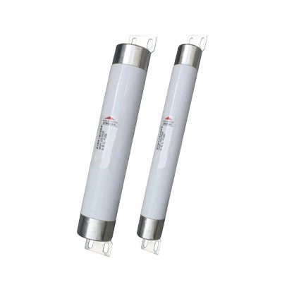
Consider a 12 kV transformer primary feeder inside a manufacturing plant. The utility service can deliver 25 kA of fault current, but the connected transformer is only rated for 0.5 seconds at that level. A current‑limiting fuse ahead of the transformer reduces the peak fault current and limits I²t to a fraction of the transformer’s withstand curve, effectively preventing internal winding damage. When you layer in arc flash hazard reduction, the fuse’s fast clearing can drop the incident energy from “extreme danger” to “manageable PPE category,” often without adding complex relays. You can explore how protection schemes for power transformers integrate these devices to mitigate arc flash hazards and protect critical assets.
Now shift to a motor control center (MCC) feeder in a process line. Frequent starts, phase loss, and occasional jam faults are everyday events. A circuit breaker lets you reset and restart quickly. If selectivity is required with downstream motor protection relays, the adjustable trip settings allow you to dial in a 0.2‑second delay while still clearing a major fault in under 5 cycles. The breaker’s local/remote operation also means you can test the circuit during scheduled maintenance without exposing personnel to the bus voltage.
Neither scenario makes the other device “wrong.” The transformer feeder values energy limitation above all; the MCC feeder values resettability and adjustability.
From Comparison to Selection: Your Next Steps
You now have a clear logic: evaluate the fault current severity, resettability needs, coordination complexity, and lifecycle cost. Once you have clarified these decision factors, comparing the specific specifications of available options becomes the logical next step. For circuits where limiting let‑through energy is the dominant requirement, reviewing Fuyi’s current‑limiting fuse series for high fault‑current scenarios will give you concrete data on interrupting ratings and I²t characteristics. For installations where a coordinated fuse‑breaker scheme might offer the best of both worlds, a practical method for achieving reliable coordination between fuses and breakers in your network can walk you through the selectivity design process without oversimplifying the engineering.


-Temperature-Controller-1.webp)