


 Aug 10,2026
When a blown fuse indicator on your medium-voltage switchgear activates, the immediate question is not just "which fuse blew" but "what caused it to blow." The indicator tells you that a fuse has operated—it does not tell you why. Tracing the root cause requires a systematic approach that examines the fuse itself, the downstream circuit, and the upstream protection coordination. This article provides a step-by-step guide to fault tracing after a high-voltage fuse blown indicator activation, helping you restore service safely and prevent recurrence.
What Does a Blown Fuse Indicator Actually Tell You?
A blown fuse indicator is a mechanical or electrical device built into a fuse or fuse holder that provides a visible signal when the fuse element has melted. Common indicator types include:
-
Pop-up pins or flags that extend outward from the fuse body when the fuse opens
-
LED indicators that illuminate when the fuse circuit is interrupted
-
Striker pins that trigger auxiliary switches or mechanical flags
The indicator confirms that the fuse has interrupted current flow. However, the indicator alone does not identify the fault type, location, or severity. That information must be obtained through systematic investigation.
Why Do Medium-Voltage Fuses Blow? Common Root Causes
Understanding why a fuse operates is the first step in tracing the fault. Medium-voltage current-limiting fuses, typically used in 6–35kV systems, can blow for several reasons:
| Cause Category | Specific Causes | Typical Indicators |
| Overcurrent faults | Short circuits, phase-to-phase faults, phase-to-ground faults | Sudden operation, often accompanied by protective relay tripping |
| Equipment failure downstream | Transformer internal faults, cable insulation breakdown, switchgear failure | Fuse operates on transformer or feeder circuit |
| Transient events | Lightning surges, switching transients, inrush currents | Operation during storms or switching operations |
| Fuse fatigue | Repeated inrush currents, thermal cycling, aging | Premature operation below rated fault current |
| Coordination issues | Incorrect fuse sizing, poor selectivity with downstream devices | Nuisance blowing under normal operating conditions |
| Installation issues | Loose connections, inadequate clearance, contaminated fuse holder | Repeated failures in same position |
Important: A blown fuse is almost always a symptom of an underlying condition, not the problem itself. Replacing the fuse without identifying the root cause risks repeated failures and potential equipment damage.
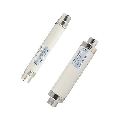
Step-by-Step Fault Tracing Procedure
Step 1: Safety First – Isolate and Lock Out
Before approaching any blown fuse, treat all equipment as energized until proven de-energized. Follow these precautions:
-
Open the upstream disconnecting switch or circuit breaker
-
Apply lockout/tagout (LOTO) procedures
-
Verify zero voltage using a properly rated voltage detector on all three phases
-
Ground all phases before proceeding
Warning: Medium-voltage fuses are current-limiting devices that operate under fault conditions. Even after isolation, some stored energy may remain in capacitive or inductive components.
Step 2: Visually Inspect the Fuse and Indicator
Once the circuit is isolated and verified de-energized:
-
Document the indicator status – Take a photo of the indicator position before any handling
-
Check all three phases – In a three-phase system, more than one fuse may have operated
-
Examine the fuse body – Look for:
-
Cracks or damage to the fuse barrel
-
Signs of arcing or tracking on the exterior
-
Discoloration that may indicate overheating
-
Sand or filler leakage (indicating fuse body breach)
-
Some fuse holders feature a striker mechanism that triggers a mechanical flag or auxiliary contact when the fuse operates. Verify that this mechanism has functioned correctly and has not been damaged.
Step 3: Identify Which Phase and Which Circuit
Determine the affected circuit and phase:
-
Check switchgear mimic diagrams or one-line drawings
-
Identify the fuse position (e.g., "Feeder 3, Phase B")
-
Note any associated protective relay operations
-
Review event logs from protection relays or SCADA systems
The phase and circuit information helps narrow down the fault location. A fault on Phase B of a transformer feeder points to different possible causes than a fault on Phase C of a capacitor bank.
Step 4: Remove and Test the Fuse
With the circuit isolated and verified de-energized, remove the fuse from its holder:
-
Use appropriate PPE – including voltage-rated gloves and face protection
-
Follow the fuse holder manufacturer's removal procedure
-
Test the fuse for continuity using a multimeter:
-
Set the meter to resistance (ohms) or continuity mode
-
Place probes on both end caps of the fuse
-
A reading of infinite resistance (OL) confirms the fuse is open
-
A reading of near-zero ohms indicates the fuse is still intact (contradicting the indicator—investigate further)
-
-
Compare to a new fuse – if available, compare resistance values
Step 5: Inspect the Fuse Holder and Connections
A blown fuse indicator can sometimes activate due to issues in the holder itself, not the fuse element:
-
Check for loose connections that may have caused arcing
-
Inspect contact surfaces for pitting, oxidation, or overheating
-
Verify spring tension on fuse clips is adequate
-
Look for tracking marks or carbon trails on insulating surfaces
Remember: A faulty holder can cause a fuse to blow prematurely or can prevent a good fuse from making proper contact.
Step 6: Investigate the Downstream Circuit
The most common cause of fuse operation is a fault downstream of the fuse:
| Downstream Equipment | What to Check |
| Transformer | Winding resistance, insulation resistance (Megger), oil level/gas analysis (if oil-filled), bushing condition |
| Cable | Insulation resistance, partial discharge testing, visual inspection of terminations |
| Switchgear | Visual inspection of busbars, insulators, and connections; check for signs of tracking or arcing |
| Load equipment | Motor insulation, capacitor bank condition, any recent maintenance or modifications |
Note: In some medium-voltage systems, the fuse protects a voltage transformer (PT). XRNP series fuses are specifically designed for PT protection with very low rated currents (e.g., 0.2A, 0.5A). If a PT fuse blows, the fault may be internal to the PT itself.
Step 7: Review Protection Coordination
Even if no obvious fault is found, consider:
-
Was the fuse correctly sized for the application?
-
Are there upstream or downstream devices that should have operated first?
-
Have there been system changes (load increases, new equipment) since the fuse was last replaced?
-
Does the fuse rating coordinate with the next protective device in the sequence?
Incorrect fuse selection—such as using an XRNT fuse (for power transformers) where an XRNP fuse (for PTs) is required—can lead to misoperation.
Blown Fuse Indicator Troubleshooting Checklist
Use this checklist when responding to an activated blown fuse indicator:
| Action |
|---|
| Isolate and lock out the circuit |
| Verify zero voltage on all three phases |
| Document indicator status and fuse position |
| Visually inspect all three fuses |
| Identify affected phase and circuit |
| Remove and continuity-test the fuse |
| Inspect fuse holder and connections |
| Investigate downstream equipment (transformer, cable, switchgear) |
| Check for transient events (lightning, switching) |
| Verify fuse rating and coordination |
| Replace only after root cause is identified |
| Test system before returning to service |
Common Mistakes to Avoid
Replacing the fuse without finding the cause – The new fuse will likely blow again, potentially causing more damage
Ignoring other phases – In some fault types, more than one fuse may have been stressed even if only one indicator activated
Using an incorrectly rated replacement – Always verify the fuse rating, type (e.g., XRNT vs XRNP), and standard (DIN vs BS)
Failing to test the circuit after replacement – Always perform insulation resistance tests and, where possible, primary injection tests before returning to service
Overlooking environmental factors – Contamination, humidity, and temperature can all affect fuse performance
Frequently Asked Questions
Q1: Can a blown fuse indicator activate if the fuse is not actually blown?
Yes. In some cases, the indicator mechanism itself can fail or be triggered by mechanical shock. A continuity test of the fuse element is the only reliable way to confirm whether the fuse has actually opened.
Q2: How do I know if the fault is upstream or downstream of the fuse?
If the fuse has blown, the fault is almost always downstream of the fuse, as the fuse protects the circuit ahead of the load. However, upstream issues like voltage surges can cause downstream fuses to blow. Check upstream protection devices (relays, breakers) for any concurrent operations.
Q3: What is the difference between XRNP and XRNT fuses, and why does it matter for fault tracing?
XRNP fuses are designed for voltage transformer (PT) protection with very low rated currents (0.2A–0.5A). XRNT fuses are for power transformer protection with higher ratings. If an XRNT fuse is mistakenly used in a PT circuit, it may not clear low-level PT faults, leading to equipment damage.
Q4: How long should I wait before replacing a blown fuse?
Do not replace a blown fuse until you have completed a full fault investigation and identified the root cause. Premature replacement without investigation risks repeated failures and potential safety hazards.
Q5: Can lightning cause a medium-voltage fuse to blow without leaving visible damage?
Yes. Lightning surges can cause fuse operation through transient overcurrents. The fuse may show no external damage, and downstream equipment may test normal. In such cases, check surge arrester status and consider installing additional surge protection if this is a recurring issue.
Q6: What should I do if the new fuse blows immediately after installation?
Immediate re-blowing indicates a hard fault downstream. Do not install another fuse. Instead, perform thorough insulation testing on the downstream circuit and equipment before attempting another replacement.
Conclusion
A blown fuse indicator activation is a clear signal that your medium-voltage fuse has operated—but it is only the beginning of the investigation. The root cause may be a simple overcurrent event, a developing equipment fault, or a coordination issue that requires system-level review. Never replace a blown fuse without first tracing the fault. The systematic approach outlined above—isolate, inspect, test, investigate, and verify—will help you restore your system safely and reduce the likelihood of recurrence.
For assistance with fuse selection, replacement, or technical support, contact our engineering team or review our medium-voltage fuse product range for available configurations and specifications.


-Temperature-Controller-1.webp)