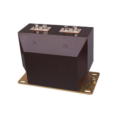
The LZZBJ9-10C is a high-performance indoor current transformer featuring epoxy resin cast insulation and a fully enclosed pillar-type structure. Designed for use in AC power systems operating at frequencies of 50–60 Hz with rated voltages up to 10 kV and maximum voltages up to 12 kV, it provides accurate power measurement, reliable current monitoring, and effective relay protection.
IEC Standard Compliance:IEC 61869-2
Robust Insulation
Epoxy resin cast construction ensures excellent electrical insulation, mechanical strength, and long-term reliability; resistant to pollution and humidity
Versatile Application
Ideal for integration into air-insulated switchgear, medium voltage distribution equipment, and various types of switchgear installations
High Current Capacity
Rated primary current up to 3150A, suitable for a wide range of medium voltage applications
Standards Compliance
Manufactured in accordance with GB 1208 and IEC 60044-1, ensuring international quality and safety benchmarks.
| Model | LZZBJ9-10C | |
|---|---|---|
| Rated voltage | 10 kV | 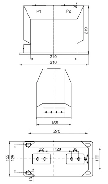 |
| Maximum voltage | 12 kV | |
| Rated frequency | 50/60 Hz | |
| Rated insulation level | 12/42/75 kV | |
| Rated primary current | 5~3150A | |
| Rated secondary current | 5A or 1A | |
| Power-frequency withstand voltage (primary to secondary and to earth) |
42 kV/1 min | |
| Power-frequency withstand voltage (secondary to secondary and to earth) |
3 kV/1 min | |
| Lightning impulse withstand voltage | 75 kV | |
| Load power factor | cosφ=0.8 (lagging) | |
| Partial discharge | ≤20pC (conforming to GB5583-85) | |
| Instrument security factor | FS≤10 | |
Service Conditions
Installation: Indoor use only
Ambient Temperature: -15°C to +40°C (daily average not exceeding +30°C)
Altitude: ≤ 1,000 m
Humidity: Average relative humidity ≤ 95% over 24 hours
Pollution Level: Class II
Environment: Free from significant dust, smoke, corrosive gases, vapor, or salt; no severe vibration or impact
Structural Overview
The transformer is fully cast in epoxy resin with a compact pillar-type design, providing maintenance-free operation and suitability for installation in any position or direction
Primary terminals are clearly marked as P1 and P2; secondary terminals are labeled sequentially (e.g., 1S1, 1S2, 2S1, 2S2) for easy identification and subtractive polarity wiring
Available in multiple variants (C1, C2) with different dimensional configurations to suit various installation requirements



-Temperature-Controller-1.webp)